The humanoid, including our specy, as a dynamical plant is still a mystery-shrouded inner-universe to be explored. Evolution of humanoid robots to the true assistants of us requires much further advancement of both control theory and mechatronics. Until then, they will have been threats even for researchers. A dilemma is that researchers, who aim at realizing much more dynamic, flexible and robust control system, can only study treatable motions, while the robot lack of such high mobility. What we need is a small and light robot with strong and reliable body. That is the very motivation of UT-mu project, since 2002.
Just so happened that some manufacturers began to provide small motors, gears, etc. developed in the same process with industrial high-spec products and mountable in robots with about 50 cm tall. Now, we can design highly transparent humanoid robot systems ourselves, choosing commonly available mechatronic components. They are not more fruits of secret technologies of some companies. Nevertheless, it is still a problem how to mount various components into the restricted space and to keep sufficient rigidity and wide motion range simultaneously in such small bodies. One purpose of this project is to provide commonly available design methodology of miniature humanoid robots among many research organizations.
|
Name: | UT-mu |
| Pop-name: | mighty | |
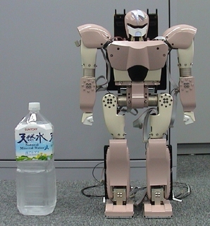
| Height: | 58[cm] | |
| Weight: | 6.5[kg] | |
| Main structure: | AZ91D(magnesium alloy) | |
| density=1.81[kg/cm^3] | ||
| Num.of joints: | 23 | |
| neck 3(unactuated) | ||
| arm 4x2 | ||
| leg 6x2 | ||
| Power source: | NiH battery or external supplier | |
| Voltage: | 24V | |
| Main CPU: | Geode GX1 | |
| Actuator: | coreless DC motor | |
| Gear: | harmonic drive gear |
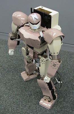
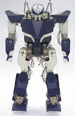
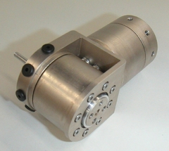
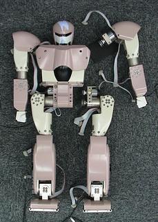
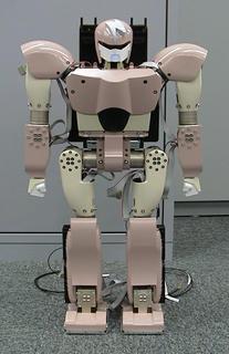
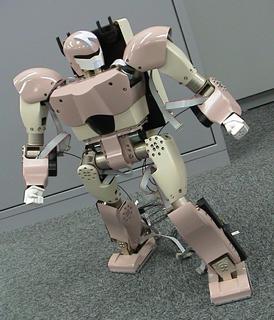
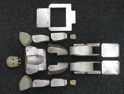
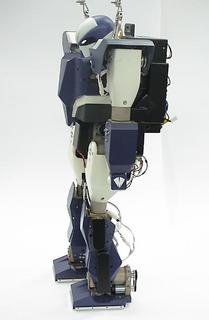
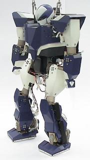
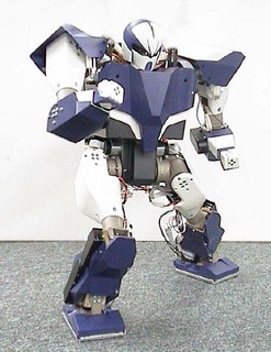
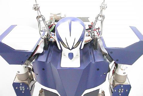
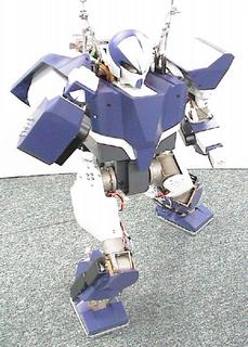
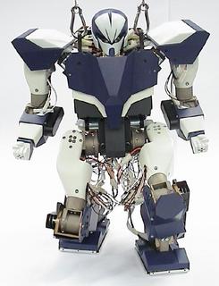
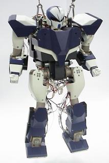
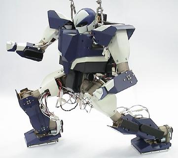
UT-mu is our prototype, completed in 2003. It is nicknamed "mighty" with a desire to be a mighty robot. All the joints feature a combination of coreless DC motor manufactured by maxon(4.5W×2:shoulder-rotational, 6.5W×4:shoulder-abductional, elbow, hip-rotational, 11W×12:reminders) and harmonic drive gears by Harmonic Drive Systems(dec.ratio 100:1). The key to save size and weight even with such high-spec motors and gears is its modularized joint design with ortho-axis-coupled gear units and magnesium-alloy-casting exoskeletal structure.
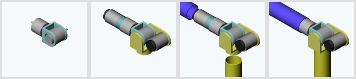
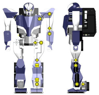
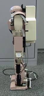
The above illustrates the basic structure of joints. "Humanoid" in terms of structure has one charactor that many pairs of adjacent joint axes are mutually parpendicular. Based on this fact, we designed ortho-axis-coupled gear unit with two harmonic drive gears. Assigning motors to each input axis and connecting those joint modules by thin-shelled(t=0.8-2.0) magnesium-alloy-casting exoskeletons, we can
UT-mu is distiguished from other robots by its unique joint assignment shown above.
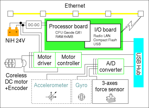
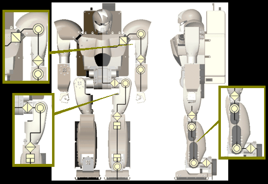
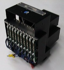
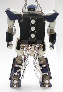
The above shows the hardware system of UT-mu. It is an independent system, having the processor board and battery within, and excluding any cables from outer resources which disturbs robot's motion. The processor board is CARD-PCI/GX(EPSON) which features CPU Geode GX1(National Semiconductor) with a customized I/O board(Fujitsu Automation). Communication with ethernet is ensured via wireless LAN card(melco), so that it can be remotely operated. It also has the internal USB LAN which branches at USB Hubs(Sanwa supply), and communicates with actuator drivers and A/D converters. The DC motors are controlled by the motor controller iMCs01 + amplifier iMDs03(iXs research corp.). The input signal from sensors, which includes the gyro sensor MG2(Microstone), the accelerometer MA3(Microstone) and the 3-axis force sensor PicoForce(NITTA), are processed at A/D converter iMCs03(iXs research corp.).
[Gallery]
This project was supported by "Robot Brain Project" under the Core Research for Evolutional Science and Technology (CREST) program of the Japan Science and Technology (JST) Corporation.
|
Name: | UT-mu2 |
| Pop-name: | magnum | |
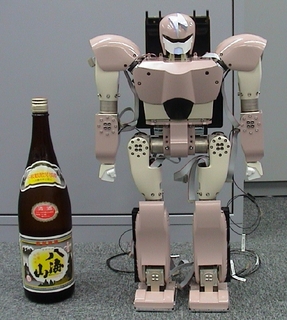
| Height: | 54[cm] | |
| Weight: | 7.5[kg] | |
| Main structure: | AZ91D(magnesium alloy) | |
| density=1.81[kg/cm^3] | ||
| Num.of joints: | 23 | |
| neck 3(unactuated) | ||
| arm 4x2 | ||
| leg 6x2 | ||
| Power source: | NiH battery or external supplier | |
| Voltage: | 24V | |
| Main CPU: | Au1100 | |
| Actuator: | coreless DC motor | |
| Gear: | harmonic drive gear |
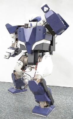
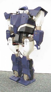
UT-mu2, completed in 2005, is the second version of the series. "magnum" is nichnamed with a wish to give a more gallant air than mighty. It is formed of rectilinear, while mighty is in a sweeping form. The mechanical structure adheres that of UT-mu -- modularized joints + magnesium exoskeleton -- and is improved to
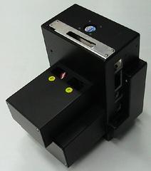
The point which required improvement of design was at its electronics system. Those systems for small robots like UT-mu series tend to be sticked into the narrow space in the body. It often leads to knotty maintenance and even damage of circuits and cables. AnimatoCore was developed in accordance with an idea that a stand-alone core control system particularly for robots including batteries and DC-DC converters could simplify the total robot design could be shared in various robotic systems.
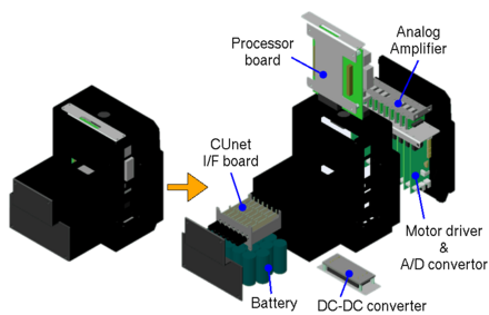
Another pending issue was the media of the internal network. In the cource of the development of UT-mu, we found that USB has some drawbacks for realtime communication, mainly due to the procedural complexity. Then, we chose CUnet(StepTechnica), which realizes widely-ranged multi-CPU network on shared memory, and constructed the internal communication network between the main processor and distributed motor/sensor controllers.

The above is the hardware system diagram of UT-mu2. You can find the core parts of the system is all involved in AnimatoCore. It also features rate gyro CRS-03(Silicon Sensing Systems), accelerometer GSX01001T(Matsukyu) and three-axis force sensor PicoForce(NITTA).
[Gallery]
This project was supported partly by Category ``S'' of Grant-in-Aid for Scientific Research, Japan Society for the Promotion of Science (JSPS), and partly by Project for the Practical Application of Next-Generation Robots in The 21st Century Robot Challenge Program, New Energy and Industrial Technology Developemnt Organization (NEDO).
Tomomichi Sugihara, Kou Yamamoto
We'd like to make a cordial acknowledgment to Prof. Masafumi Okada, Mr. Shingo Chiyoda, Mr. Tetsuya Shinohara, Mr. Akihiko Murai, Dr. Kay Okada, Dr. Ken'ichiro Nagasaka, Mrs. Eri Nagasaka, Dr. Fuminori Yamasaki, Dr. Noriaki Mitsunaga, Mr. Tatsuhito Aono and many other people. If not for their assistance, UT-mu series could hardly be completed.